1Overview
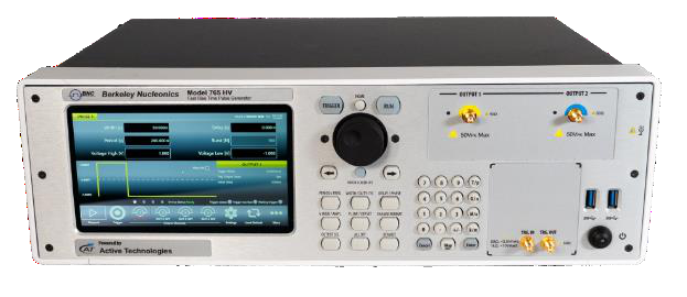
The Model 765-HV Pulse Generator is a feature-rich pulse and delay generator with 1 or 2 channels of completely programmable pulse and delay generation. The instrument offers many improvements over the previous design: faster transition times, narrow pulses, broader and more accurate amplitude control, and a redesigned user interface.
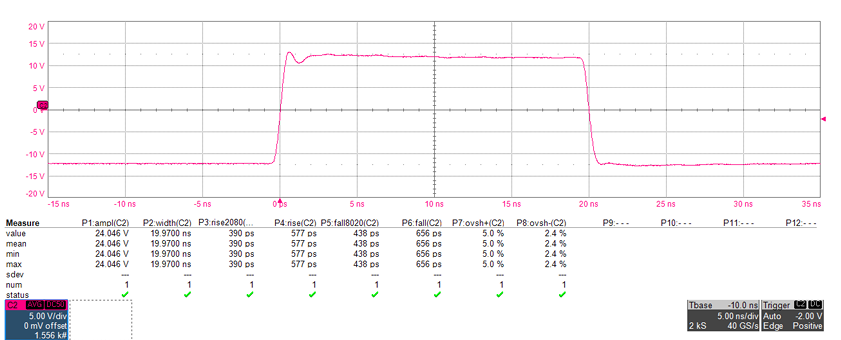
The 765-HV delivers up to 50 Vpp into 50 Ohm. Rise and fall times are 630 ps at 50 Vpp (10% to 90%), and edge time drops to 400 ps measured 20% to 80%. A proprietary front-end and analog edge converter virtually eliminate overshoot (less than 5.0% typical at 25 Vpp to 50 Vpp) and ringing. The pulse-width range spans 1 ns to (period minus 1 ns), so a single instrument covers narrow gating pulses and long intervals out to an 8 s period.
The 765-HV traces its design heritage to DEI, now a division of Berkeley Nucleonics. Each unit ships with a comprehensive Software Development Kit (SDK) at no additional charge.
2How It Works
Intuitive User Interface
The front panel includes a 7 inch touchscreen and tactile controls for most operations. The touchscreen gives a smartphone-like architecture with gesture control: the primary channel controls and programming options are easy to navigate, with a swipe gesture to move from channel to channel. Combining multiple pulses on one output can be graphically controlled and is easily identified on the screen. A rotary encoder and backlit pushbuttons provide a familiar alternative for users who prefer front panel controls. Dialing the encoder changes a value in continuous, analog fashion; pushing the encoder in moves the adjustment from fine to coarse.
Fast Rise Times and Plenty of Range
The Model 765-HV offers 630 ps rise and fall times (at 50 Vpp, 10% to 90%) over a large time domain. The front-end electronics circuit and a new analog edge converter are integrated using a proprietary technology that virtually eliminates overshoot (less than 5.0% typical) and ringing.
Multi-pulse Mode
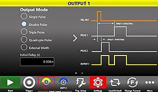
The Model 765-HV allows users to combine four digitally programmed pulses on each output. This supports complex timing sequences and repetition rates to 400 MHz. The graphical user interface gives an easy representation of the outputs on a given channel, with independent delay and width settings from a common trigger.
Programming
The remote programming uses common SCPI commands, ensuring compatibility with a wide range of development environments. Visual Studio, .NET, LabView, LabWindows/CVI, and MatLab are all supported. A networking feature allows users to apply the VXI-11 LAN protocol to network the instrument for printing, file sharing, internet access, and remote login.
Inputs and Outputs
The Pulse Out connectors are DC coupled SMA connectors with 50 Ohm impedance and strain-relief panel mounts. Pulse out settings can be independently positive or negative (0V to plus or minus 25V, adjustable). The Trigger Input is an SMA connector with programmable impedance and threshold (50 Ohm at plus or minus 3.5V, or 1k Ohm at plus or minus 10V), a 10 mV threshold resolution, and an Autosense function that measures the current trigger input level. The Trigger Out is an SMA connector with 50 Ohm impedance and a 1.8V to 3.3V adjustable output. Two USB 3.0 ports sit on the front panel; the rear panel adds external monitor ports (HDMI, VGA), LAN, and audio.
3Specifications
The values below are taken directly from the published Model 765-HV datasheet (Rev V1.3). All performance is specified into a 50 Ohm load unless noted.
Pulse Out Limits
| Parameter | Min | Max |
|---|---|---|
| Voltage | -25.0 V | +25.0 V |
| Amplitude | 100 mVpp | 50 Vpp |
| Offset | -25 V | +25 V |
| Width | 1 ns | Period − 1 ns |
| Period | 5 ns | 8 sec |
| Frequency | 0.125 Hz | 200 MHz |
| Delay | 0 sec | Period |
Timing
| Parameter | Specification |
|---|---|
| Pulse period range | 5 ns to 8 sec. |
| Pulse period resolution | 10 ps |
| Pulse period RMS jitter 1 | 15 ps |
| Pulse frequency range | 0.125 Hz to 200 MHz (single pulse mode); 0.25 Hz to 400 MHz (double, triple and quadruple pulse mode) |
| Pulse frequency accuracy | ± 2 ppm max |
| Pulse width range | 1 ns to (period − 1 ns) |
| Pulse width resolution | 10 ps |
| Pulse width accuracy | ± (1% + 0 ps) 2 |
| Pulse width RMS jitter 1 | < 10 ps |
| Pulse delay range (single/double/triple/quadruple) | 0 ps to period |
| Pulse delay resolution | 10 ps |
| Pulse delay accuracy | ± (0.1% + 100 ps) |
Output Specifications (50 Ohm load)
| Parameter | Specification |
|---|---|
| Impedance | 50 Ohm nominal |
| Amplitude range pk-pk | 100 mVpp to 50 Vpp |
| Amplitude resolution | 10 mV |
| Amplitude absolute accuracy | ±(2% of amplitude p-p + 2% of |DC Offset| + 200 mV) |
| DC Offset range | 0V or ± 25V adjustable |
| DC Offset resolution | 10 mV |
| Baseline Offset range | -25V, -12.5V, 0V, +12.5V, +25V (software selectable) |
| Baseline Offset resolution | 12.5 mV |
| Rise Time (20% to 80%, Offset = 0V) | < 400 ps (up to 50 Vpp amplitude) |
| Rise Time (10% to 90%, Offset = 0V) | < 570 ps (up to 25 Vpp amplitude); < 630 ps (up to 50 Vpp amplitude) |
| Fall Time (20% to 80%, Offset = 0V) | < 430 ps (up to 25 Vpp amplitude); < 530 ps (up to 50 Vpp amplitude) |
| Fall Time (10% to 90%) | < 640 ps (up to 25 Vpp amplitude); < 840 ps (up to 50 Vpp amplitude) |
| Overshoot | < 8% (up to 25 Vpp amplitude); < 5% (25 Vpp to 50 Vpp amplitude) |
| Channel to Channel RMS jitter 1 | < 15 ps |
| Initial Delay | 0s to 8s (retriggerable delay off); 0s to 2.5 us (retriggerable delay on) |
1 All channels at the same frequency in Single Pulse mode and Continuous mode. 2 With Offset not equal to 0V the width can deviate from this specification depending on the Offset voltage and other parameters.
Trigger
| Parameter | Specification |
|---|---|
| Trigger input impedance | 50 Ohm or 1K Ohm programmable |
| Trigger input range | ± 3.5 V (50 Ohm input impedance); ± 10 V (1K Ohm input impedance) |
| Minimum detectable amplitude | < 50 mVpp |
| Threshold range | ± 8V |
| Threshold resolution | 10 mV |
| Threshold accuracy | ± 100 mV |
| Max. input frequency | 40 MHz |
| Min. pulse width | 1 ns |
| Max. external width mode input frequency | 400 MHz (duty cycle = 50%) |
| Edge selection | Positive, negative, both |
| Prescaler (for every channel) | 0 to 65535 |
| Trigger output impedance | 50 Ohm nominal |
| Trigger output amplitude (open load) | 1.8V to 3.3V adjustable |
| Trigger output amplitude resolution | 1 mV |
| Trigger output amplitude accuracy | ± 1% |
| Delay (trigger in to trigger out) | < 100 ns |
| RMS jitter (trigger in to trigger out) | < 30 ps (Trigger IN frequency ≤ 15 MHz) |
| Trigger output width | 10 ns (single, burst mode); Period/2 (continuous mode) |
| Trigger output initial delay | 0s to 8s (continuous mode); 0s to 2.5 us (single, burst, gated mode) |
Internal Timer
| Parameter | Specification |
|---|---|
| Time range (frequency range) | 25 ns to 42.9 sec (40 MHz to 23.3 mHz) |
| Time resolution | 1 ps |
| Frequency accuracy | ± 2 ppm max |
External Clock IN
| Parameter | Specification |
|---|---|
| Connector type | SMA on rear panel |
| Input impedance | 50 Ω, AC coupled |
| Input voltage range | -5 dBm to 4 dBm sine or square wave (rise time T10-90 < 1 ns and duty cycle from 40% to 60%) |
| Damage level | +8 dBm or ±15 VDC Max |
| Frequency range | 10 MHz to 100 MHz |
External Clock OUT
| Parameter | Specification |
|---|---|
| Connector type | SMA on rear panel |
| Output impedance | 50 Ω, DC coupled |
| Frequency | 10 MHz or External Clock IN frequency |
| Accuracy | ± 2 ppm max |
| Aging | ± 1.0 ppm/year max |
| Amplitude | Square wave: 0V to 1.25 V into 50 Ω, 0V to 2.5 V into High Z |
Programmability
| Parameter | Specification |
|---|---|
| Trigger modes | Single, continuous, burst, gated |
| Multiple pulse modes | Single, double, triple, quadruple, external width |
Power
| Parameter | Specification |
|---|---|
| Voltage range | 100-240 VAC ±10% |
| Frequency range | 47-63 Hz |
| Max. power consumption | 300 W |
Environmental Characteristics
| Parameter | Specification |
|---|---|
| Temperature (operating) | +5 °C to +40 °C (+41 °F to 104 °F) |
| Temperature (non-operating) | -20 °C to +60 °C (-4 °F to 140 °F) |
| Humidity (operating) | 5% to 80% relative humidity with a maximum wet bulb temperature of 29 °C at or below +40 °C (upper limit de-rates to 20.6% relative humidity at +40 °C). Non-condensing. |
| Humidity (non-operating) | 5% to 95% relative humidity with a maximum wet bulb temperature of 40 °C at or below +60 °C (upper limit de-rates to 29.8% relative humidity at +60 °C). Non-condensing. |
| Altitude (operating) | 3,000 meters (9,842 feet) maximum at or below 25° |
| Altitude (non-operating) | 12,000 meters (39,370 feet) maximum |
EMC and Safety
| Parameter | Specification |
|---|---|
| Safety | EN61010-1 |
| Main Standards | EN 61326-1:2013 — Electrical equipment for measurement, control and laboratory use — EMC requirements — Part 1: General requirements |
| Immunity | EN 61326-1:2013 |
General Characteristics
| Parameter | 765-HV-1C | 765-HV-2C |
|---|---|---|
| Display | 7 inch, 1024x600, capacitive touch LCD | |
| Operating system | Windows 10 | |
| External dimensions | W 445 mm – H 135 mm – D 320 mm (3U 19" rackmount) | |
| Weight | 21.4 lbs (9.7 Kg) | |
| Front panel connectors | OUTPUT1 (SMA), TRG.IN (SMA), TRG.OUT (SMA), 2 USB 3.0 ports | OUTPUT1 (SMA), OUTPUT2 (SMA), TRG.IN (SMA), TRG.OUT (SMA), 2 USB 3.0 ports |
| Rear panel connectors | External Monitor ports (HDMI, VGA), 2 USB 2.0 ports, 2 USB 3.0 ports, 3 COM ports, 2 Ethernet ports (10/100/1000BaseT, RJ45), Audio In/Out ports, 2 PS/2 keyboard and mouse ports, External Clock IN (SMA), External Clock OUT (SMA) | |
| Hard disk | 128 GB SSD | |
| Processor | Intel® Celeron J1900, 2 GHz (or better) | |
| Processor memory | 8 GB | |
4Applications
The Model 765-HV pairs high edge speed with a wide amplitude and timing range, which fits it to demanding test and emulation work. Target applications include:
- Big physics. Programmable timing and amplitude across one or two channels for accelerator and beam-line instrumentation.
- Collider experiments. Fast, accurate pulse and delay generation for synchronized experiment timing.
- Laser modulation. Narrow, fast pulses for gating and modulating laser sources.
- Radar and sonar systems. Fast pulse generation for testing and emulating complex detection systems.
- Semiconductor test. High edge speed combined with high dynamic range to test and validate integrated circuits.
Application Idea: Semiconductor Test
Modern silicon demands high-quality, high-fidelity test systems. Many pattern generators offer a good combination of performance but are limited in edge speed and dynamic range. The 765 series offers both high speed and high dynamic range, combined with an easy-to-use interface and pulse-mixing capabilities in one or multiple channels. This makes it well suited to testing components and validating integrated circuits. DTG functionality can be created by synchronizing one or more 765 series units (2 channels each).
Application Idea: Radar
Army and navy programs may require fast pulse generation for testing or emulation. Radar and sonar systems pair well with these generators to test and validate complex detection systems. The 765 series is a good fit where a large channel count is required and the cost and complexity of DAC solutions is too high. Electromagnetic systems used in military applications may be tested by 765 pulse generators, including pulsed electron beam or X-ray sources, flash X-ray radiography, lightning pulse simulators, and high-power microwave modulators.
5Ordering Information
| Model / P/N | Description |
|---|---|
| 765-HV-1C | 1 Channel HV Pulse Generator |
| 765-HV-2C | 2 Channel HV Pulse Generator |
| 765-RMKit 19 | Rack Mount Kit for the 765-X |
Configuration depends on the required channel count and the rep-rate and amplitude profile of your application. Contact Berkeley Nucleonics to confirm the configuration that fits your test.