Model 845-M 10 MHz to 20 GHz Low Noise Microwave Synthesizer
An ultra-compact, fast, low power consumption frequency synthesizer with USB & LAN interface. Milli-Hz frequency resolution, a high-stability internal reference, and switching speeds down to 25 µs, in a flange-mount module that runs from a single 6 V DC supply.
The Model 845-M is a wideband low phase noise synthesizer operating from 10 MHz to 20 GHz. The nominal output power is +23 dBm. The module has milli-Hz frequency resolution and uses a high-stability internal reference. The internal reference can be phase-locked to a user-settable external reference. For highest phase coherence, multiple 845-M modules can be cascaded with just one master reference clock.
The Model 845-M offers dedicated sweeping capabilities with switching speeds of only 25 µs and wideband frequency modulation as well as narrow pulse modulation. The module has USB and LAN interfaces and can be controlled using the SCPI 1999 command set. Operated with an external 6 V DC supply, it consumes less than 10 watts.
Specification conditions. Specifications describe the warranted performance of the instrument for 23 ±5 °C after a 30-minute warm-up period. Typical: expected mean values, not warranted performance. Min and max: parameter range that is guaranteed by product design and/or production tested.
2Key Features
Low phase noise across the full 10 MHz to 20 GHz span.
Fast switching down to 25 µs (Option FS) for agile hopping and fast test sequencing.
FM, chirps, and pulse modulation for analog FM, linear chirp, and narrow pulse work.
Internal OCXO, external variable reference with a user-settable external reference input.
USB, LAN, and GPIB interfaces under the SCPI Version 1999.0 command set.
Milli-Hz resolution at 0.001 Hz steps.
Single 6 V DC supply, under 10 W, in a compact flange-mount module.
3Frequency, Reference & Output Power
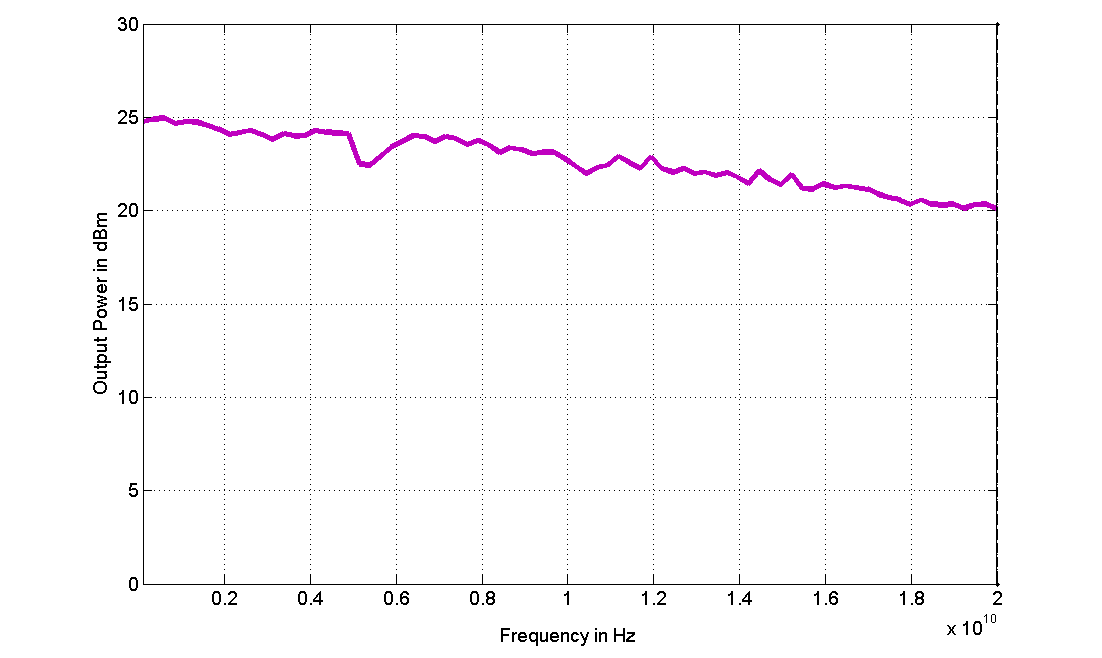
Figure 1: Output power, 0.01 to 20 GHz.
The 845-M covers 10 MHz to 20 GHz with 0.001 Hz resolution and 0.1 deg phase resolution. Output power is +23 dBm typical (18 dBm min, 26 dBm max), enough to drive mixers and frequency converters directly in many local-oscillator roles.
Signal specifications
Parameter
Min
Typical
Max
Note
Frequency range
10 MHz
20 GHz
Resolution
0.001 Hz
Phase resolution
0.1 deg
Switching speed, CW mode
1.5 ms
after SCPI command received
Switching speed, sweep / list mode
180 µs
25 µs
Option FS
Level performance
Parameter
Min
Typical
Max
Note
Output power
18 dBm
23 dBm
26 dBm
(see plot)
Reverse power protection and VSWR
Parameter
Min
Typical
Max
Note
Reverse power protection, DC voltage
7 V
Reverse power protection, RF power
23 dBm
Output impedance
50 Ohms
VSWR
1.8
Frequency reference
The high-stability internal 100 MHz reference can be phase-locked to a user-settable external reference. For highest phase coherence, multiple 845-M modules can be cascaded with one master reference clock.
Parameter
Min
Typical
Max
Note
Internal reference frequency
100 MHz
Temperature stability
±100 ppb
0 to 50 degC
Aging, 1st year
0.5 ppm
1 ppm
Aging per day
5 ppb
after 30 days operations
Warm-up time
5 min
Output of internal reference
100 MHz
Output power
0 dBm
5 dBm
Output impedance
50 Ohms
Bypass internal reference input
100 MHz
high phase synchronous mode
Phase lock to external reference
1 MHz
integer MHz
250 MHz
Reference input level
−5 dBm
0 dBm
+13 dBm
Reference bypass mode
5 dBm
+15 dBm
External reference lock range
1–250 MHz, ±1.0 ppm
Bypass 100 MHz >100 ppm
Reference input impedance
50 Ohms
4Phase Noise & Spectral Purity
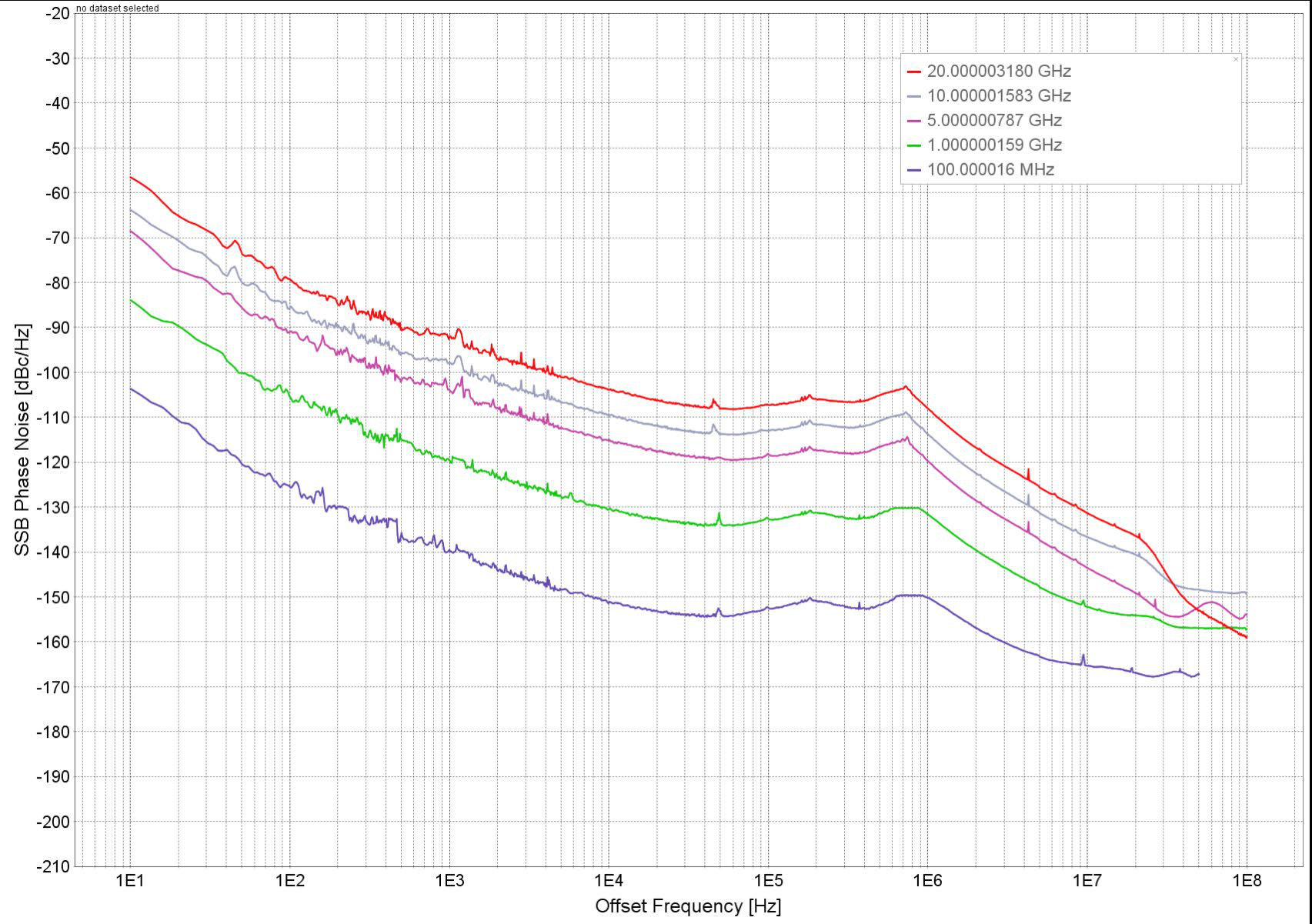
Figure 2: Phase noise performance (carriers at 100 MHz, 1, 5, 10, and 20 GHz).
Low phase noise is the defining trait of the 845-M. At a 1 GHz carrier, SSB phase noise reaches −118 dBc/Hz at 1 kHz offset and −128 dBc/Hz at 100 kHz offset, with a −150 dBc/Hz wideband floor.
Phase noise
Parameter
Min
Typical
Max
Note
SSB phase noise at 1 GHz, at 1 kHz from carrier
−118 dBc/Hz
(see also plot)
SSB phase noise at 1 GHz, at 100 kHz from carrier
−128 dBc/Hz
SSB phase noise at 1 GHz, wideband noise
−150 dBc/Hz
SSB phase noise at 10 GHz, at 1 kHz from carrier
−100 dBc/Hz
SSB phase noise at 10 GHz, at 100 kHz from carrier
−108 dBc/Hz
SSB phase noise at 10 GHz, wideband noise
−150 dBc/Hz
Spectral purity
Parameter
Min
Typical
Max
Note
Output harmonics
−15 dBc
Sub-harmonics
−75 dBc
−60 dBc
Non-harmonic spurious
−75 dBc
−60 dBc
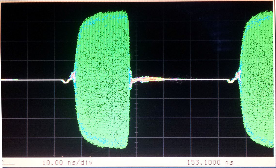
5Modulation
The 845-M supports pulse modulation from internal or external sources, wideband frequency modulation, phase modulation, and frequency chirps. An internal pulse generator with pattern and staggered-PRF capability is built in.
Sweep / list mode step time is 180 µs typical, dropping to 25 µs with Option FS for agile hopping and fast test sequencing. Sweep types are linear, logarithmic, and random.
Sweeping capability (linear, logarithmic, random)
Parameter
Min
Typical
Max
Note
Frequency sweep step time (tstep)
180 µs
25 µs
Option FS
Dwell time (tdwell)
15 µs
Trigger (TRIG IN)
The trigger input is TRIG IN at the front panel.
Parameter
Min
Typical
Max
Note
Trigger types
Continuous, single (point), gated, gated direction
Trigger source
External, bus (LAN, USB)
Trigger modes
Continuous free run, trigger and run, reset and run
Trigger uncertainty
5 µs
External trigger delay
50 µs
40 s
External delay resolution
15 ns
Trigger modulo
1
255
execute only on Nth trigger event
Trigger polarity
Rising, falling
External trigger input threshold
0.85 V
0.9 V
0.95 V
TTL compatible
External trigger input voltage range
−0.5 V
+5.5 V
TTL compatible
External trigger input hysteresis
60 mV
7General Characteristics
Parameter
Specification
Remote programming interfaces
Ethernet 100BaseT LAN interface, USB 2.0 host & device; control language SCPI Version 1999.0
Power requirements
6 V VDC; 20 W maximum
Mains adapter supplied
100–240 VAC in / 6 V 6.0 A DC out
Environmental
Levels similar to MIL-PRF-28800F Class 3/4
Operating temperature range
0 to 45 °C
Storage temperature range
−40 to 70 °C
Operating and storage altitude
up to 15,000 feet (4600 m)
Safety / EMC
Complies with applicable Safety and EMC regulations and directives
Weight
≤ 1.0 kg (2.2 lbs) net
Dimensions (W x L x H)
10.5 x 21 x 6 cm [4.13 x 8.27 x 2.36 in]
Dimensions with Option FS
10.5 x 27 x 6 cm [4.13 x 10.63 x 2.36 in]
Environmental stress: samples of this product have been type tested to be robust against the environmental stresses of storage, transportation, and end-use; those stresses to temperature, humidity, shock, vibration, altitude, and power line conditions.
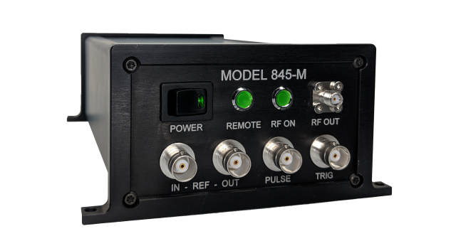
8Interfaces, Connectors & Form Factor
The 845-M controls over Ethernet 100BaseT LAN and USB 2.0 using SCPI Version 1999.0, so it slots into existing automated test frameworks with little custom code. The high-stability internal reference holds frequency, and a user-settable external reference input lets you phase-lock the module to a system clock.
The flange-mount module measures 10.5 x 21 x 6 cm [4.13 x 8.27 x 2.36 in] and weighs ≤ 1.0 kg (2.2 lbs) net. With Option FS the length grows to 27 cm [10.63 in]. The module runs from a single external 6 V DC supply.
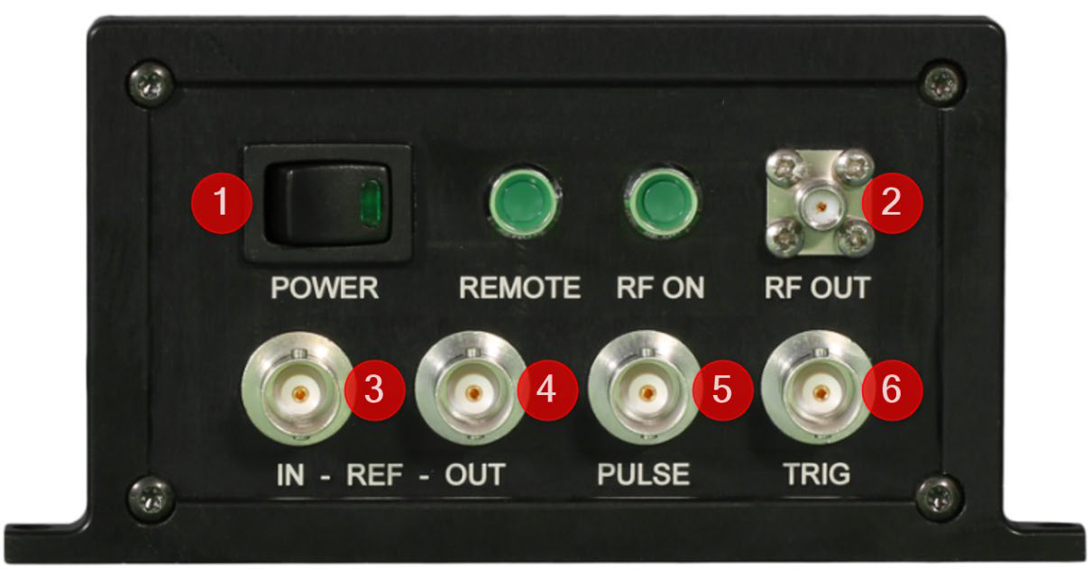
Front panel connectors
Front panel layout.
Power switch
RF connector SMA-type (female)
REF IN external reference input: BNC female
REF OUT internal reference output: BNC female
PULSE pulse modulation input: BNC female
TRIG trigger input: BNC female
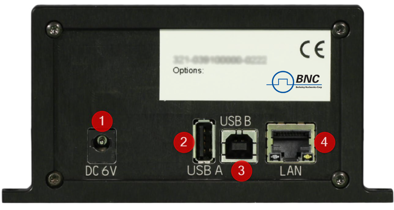
Rear panel connectors
Rear panel layout.
DC power plug (6 V, 3 A)
USB Type A
USB 2.0 host and device
LAN connection RJ-45
9Ordering Information
Host Model
Product
Description
845-M
845-M
20 GHz Synthesizer, flange-mount module
845-M
Option 1URM
19 inch 1HU rackmount enclosure
845-M
Option FS
Ultra fast switching speed
845-M
Option GPIB
GPIB interface (only with option 1URM)
10Applications
ATE (automated test equipment)
LO for frequency converters
Telecom / SatCom
System integration
11How to Order
Order the base 845-M as a 20 GHz flange-mount synthesizer module. Add Option FS for 25 µs switching, Option 1URM for the 19 inch 1HU rackmount enclosure, and Option GPIB for the GPIB interface (available only with Option 1URM). For configuration help, pricing, or a quotation, contact Berkeley Nucleonics Corp. at info@berkeleynucleonics.com or 415-453-9955.